
TO: Director, National Institute for Occupational Safety and Health
FROM: Iowa FACE Program
SUBJECT: Worker Dies When Tower Crane and Water Tower Crash to the Ground
SUMMARY
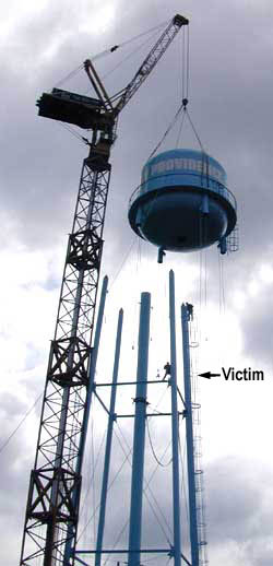
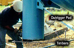
A 29-year-old worker for a water tank company was killed when the partially assembled water tower he was working on was struck by a falling portable tower crane. The man was part of a three-man crew that reconditions and relocates used water towers, this one intended for a small rural Iowa community. An independent crane company was hired to erect supports for the water tower and lift the tank into its final position. This company erected its portable tower crane adjacent to the new foundations for the water tower, as close as possible. (see Photo 1). After hoisting the tank and while swinging it into position, with just a few feet to go, the rear crane outrigger facing the water tower slipped between cribbing timbers and sank into the ground. The entire tower crane fell towards the water tower, smashing everything in its path. The victim was sitting on a horizontal strut of the water tower base (see Photo 1), approximately 80 feet in the air, preparing to adjust and tighten bracing rods once the tank was in position. Two other workers were injured, another member of the tank crew, who was positioned inside the ladder cage for the water tower, and the operator of the crane, who was sitting inside the control box of the crane 120 feet above the ground. Photo 1 was taken by a newspaper reporter a few minutes before the crane fell.
(Photo credit--Marshalltown Times Republican)
RECOMMENDATIONS based on our investigation are as follows:
1. Crane owners and operators should ensure that cranes are properly set up with the outrigger pads supported by firm stable footing.
2. Crane set-ups should be closely observed during lifting operations to detect instability caused by changing load and ground conditions.
3. Prior to crane operations, construction companies utilizing crane services as well as the crane owners and operators should evaluate the soil bearing capacity at the lift site to ensure that crane equipment and procedures are compatible with site conditions
INTRODUCTION
In July 2000, a mobile tower crane fell into an adjacent water tower, causing the death of a 29-year-old man working for a tank company that specializes in the relocation of used water towers. The Iowa FACE program became aware of the incident the next day from local news media and began an immediate investigation. A site visit was planned that same afternoon, and photographs were taken of the construction site, the crane that fell, and the smashed water tower. One investigator conducted this site visit and also returned a week later to make detailed measurements after the crane had been removed from the site. Other information was gathered from newspapers, interviews with the company erecting the water tower, a national internet forum on crane accidents, and other crane companies using this same type of mobile crane. An operator's manual was also obtained. Additional photographs were obtained from reporters who were at the scene immediately prior to and during the incident.
The employer was a small company specializing in the reconditioning and relocation of used water tanks and water towers. The company had been in business part-time for six years, and full-time for the past 15 months. The company had three employees, all three having multiple combined years of experience working with and moving water tanks. Two workers were positioned on the water tower itself, while the owner gave verbal instruction from the ground.
 The
company had a written safety program, and all three men had gone
through safety training for this type of work. Due to the complexity
of the work and the unique circumstances of every job, specific
written safety instructions were not possible. However, safety
was routinely discussed each day on the job. Workers were aware
of the risks and wore proper fall-protective equipment, including
safety harnesses and shock-absorbing lanyards. The victim had
seven year's experience working with water tanks and two year's
experience with this tank company. This was the first fatal accident
for this tank company.
The
company had a written safety program, and all three men had gone
through safety training for this type of work. Due to the complexity
of the work and the unique circumstances of every job, specific
written safety instructions were not possible. However, safety
was routinely discussed each day on the job. Workers were aware
of the risks and wore proper fall-protective equipment, including
safety harnesses and shock-absorbing lanyards. The victim had
seven year's experience working with water tanks and two year's
experience with this tank company. This was the first fatal accident
for this tank company.
The crane company, however, had a fatal accident
three years ago while erecting a windmill generator on top of
a 140-foot column. In that case the same type of mobile tower
crane was used. Timbers under the outriggers were placed on recently
backfilled soil adjacent to the new windmill foundation, and the
timbers sank into the loose soil, causing the tower crane to fall
with its hoisted load. (See FACE report on our website)
INVESTIGATION
The tank company was contracted to dismantle, relocate, and reassemble a water tower which had been used at a public facility. The reconditioned water tower was to be the water supply for a small rural community, population 250. The total height of the water tower was 127 feet. The water tank had a capacity of 50,000 gallons, was 22 feet in diameter, 23 feet tall, and had an empty weight of 28,000 lbs. Tank company employees considered this a small job, having worked on much larger municipal water tanks in the past.
Two months prior to this accident, a local contractor excavated the area to a depth of 18 feet and structurally filled this area to a depth of 7 feet, all according to engineering specifications received from an engineering firm that specializes in water tower construction. Structural fill dirt, which was trucked in for this, was described as gray brown lean clay trace silt. This fill was compacted to 98% of maximum, and later tested and certified (at 7 feet below grade), by an independent engineering firm as suitable for a load bearing capacity of 2000 psf. (pounds per square foot). This was the level where the foundations for the water tower were poured. The next 6 feet of soil was backfilled and compacted to 95% of maximum, which was never tested, but would likely still retain the 2000 psf. rating. The final 6-12 inches of topsoil was composed of black dirt, which had been scraped off the area prior to excavation. This top soil had no certified bearing load, for it was not compacted, but was simply to allow grass to grow in the area. The mobile crane trailer had difficulty maneuvering in this black dirt and required assistance from the excavation contractor on site.
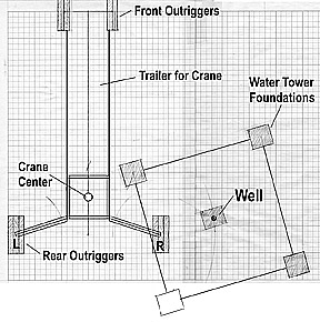
The exposed sections of the four concrete foundations for the tower were 24 feet, 10 inches apart (see Diagram). The four legs of the water tower were bolted to these concrete pads, and horizontal struts and tightening rods were in place to keep the supports square.
The last major construction procedure was to lift the reconditioned water tank onto the legs of the water tower. The in-state crane company was using a portable telescopic-type tower crane with a capacity of 30 tons. It had a platform height of 140 feet with a 50-foot boom, giving the entire crane a height of approximately 188 feet. The last crane from this manufacturer was made in 1980; therefore, this crane was at least 20 years old. It is described as more complicated than other cranes; however, it is well suited to set up and use quickly in urban settings.
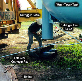
The water tank was initially unloaded about 100 feet from the water tower. The crane therefore, was first erected at a suitable location to move the water tank into the proper position for the final lift, adjacent to the water tower legs (See Photo 4). During this move, the capacity and reach of the crane was tested by "booming down" or "walking the load", i.e., extending the swing radius to 30 feet, 6 feet farther than would be required for the final lift, which required a swing radius of approximately 24 feet. The tank was kept just off the ground for the test lift in case of overloading. At this time the crane had no difficulty moving the empty tank; therefore, the water tank was placed adjacent to the water tower and the portable crane was moved into position for the final lift the next day. The crane was not tested by "booming down" at this final location prior to the lift.
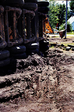
As mentioned, it was difficult for the semi-tractor to move the crane trailer into position because of the soft topsoil. Photographs show deep wheel tracks from the four sets of dual tires under the heavy trailer (See Photo 7). A local farmer with 30 years of farming experience described the soil as "hard as pavement on top, yet pure gumbo underneath". He said the soil was very difficult to work; it drained poorly, and retained moisture more than other soils. This jobsite was flat; the ground surface was dry; the temperature was in the 90s, and there was essentially no wind that day.
The tower crane was positioned at an angle to the water tower foundations (See Diagram), as close to the water tower as possible. This type of tower crane has four outriggers, two at the front, adjacent to the edges of the trailer, and two outriggers at its rear. The front outriggers are secured to the right and left sides of the transport trailer and have no lateral movement but are hydraulically driven downward to level the crane. The two rear hydraulic outriggers are on 9-foot extended beams, which give a center-to-center distance between these outriggers of 27 feet. These outriggers swing into position manually and then are pinned in place with a steel strut. Each beam is extended hydraulically forcing the outrigger pads downward to level the crane.
Each front outrigger was set on two timbers which were set directly on the ground. The timber dimensions were 85 inches long, 12 to13 inches wide, and 7 inches tall. Each rear outrigger was set on three of these timbers, which also were set on the bare ground. There was no evidence of an attempt to move the 6-12 inches of topsoil in the area; all outriggers were set directly on this black dirt. The right rear outrigger was set inside the perimeter of the new water tower, approximately 11 feet from the well opening. No plywood or steel plates were used under the timbers to distribute the load, nor were any bolts or other rigging used to secure the timbers together.
 Shortly
before the final lift, the water tank was raised a few feet off
the ground to clean up the bottoms of the support legs (Photo
4). This photograph shows a glimpse of the outrigger and cribbing
timbers that completely failed 20 minutes later. On a closer look
at the photo (Photo 5), some details are noteworthy: (1) the ground
is not level under the timbers, (2) the cribbing timber to the
right has already begun to roll out from under the pad, and (3)
there is a space between the right and middle timbers. The appearance
of the timbers in this photo is consistent with the final position
of them after the accident, as seen in Photo 6.
Shortly
before the final lift, the water tank was raised a few feet off
the ground to clean up the bottoms of the support legs (Photo
4). This photograph shows a glimpse of the outrigger and cribbing
timbers that completely failed 20 minutes later. On a closer look
at the photo (Photo 5), some details are noteworthy: (1) the ground
is not level under the timbers, (2) the cribbing timber to the
right has already begun to roll out from under the pad, and (3)
there is a space between the right and middle timbers. The appearance
of the timbers in this photo is consistent with the final position
of them after the accident, as seen in Photo 6.
This telescopic mobile tower crane can be controlled from two locations, from an elevated cab within the tower itself at a height of 130 feet, or remotely from the ground. Both positions are equal in their ability to maneuver the crane, and the remote controls are normally used for reasons of safety. For this operation, the crane operator chose to work from the elevated cab position, apparently to more clearly see the signals from other workers located on the water tower.
Two men from the tank company were positioned on the water tower itself to help "catch the iron". One was inside the ladder cage at the top of the ladder, to help with final positioning of the tank onto the water tower legs. The other man, the victim, was on a horizontal strut, preparing to position and tighten the X-bracing immediately after the tank was lowered onto the water tower (See Photo 1). The owner of the tank company was standing on the ground giving directions to the other two men.
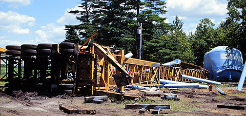
 The water
tank was raised to about 130 feet then swung over the water tower
structure to align it with the base, the procedure lasting approximately
11 minutes. The tank was vertically within 3 to 4 feet of the
water tower legs when the right rear outrigger on the tower crane
suddenly shifted and sank down between the timbers, causing the
tower to fall towards the water tower structure (See Photo 6).
The soft soil was pushed upwards, the stabilizer arm on the right
outrigger snapped, and the outrigger arm swung to the rear of
the trailer as the crane began falling. Witnesses report it took
several seconds for the crane and tower to fall to the ground,
taking nearby powerlines with it.
The water
tank was raised to about 130 feet then swung over the water tower
structure to align it with the base, the procedure lasting approximately
11 minutes. The tank was vertically within 3 to 4 feet of the
water tower legs when the right rear outrigger on the tower crane
suddenly shifted and sank down between the timbers, causing the
tower to fall towards the water tower structure (See Photo 6).
The soft soil was pushed upwards, the stabilizer arm on the right
outrigger snapped, and the outrigger arm swung to the rear of
the trailer as the crane began falling. Witnesses report it took
several seconds for the crane and tower to fall to the ground,
taking nearby powerlines with it.
 Several
people rushed to aid the three men caught in the wreckage. The
crane operator was still inside the cab area, conscious, with
facial wounds and other injuries. The man inside the ladder cage
clung to the ladder when it fell and remained conscious, suffering
only a broken ankle. The victim was unconscious and bleeding from
head injuries, without a pulse or respirations. CPR was begun
by a newspaper reporter and other bystanders and continued until
emergency crews arrived. The victim was air-lifted to a hospital,
and was pronounced dead shortly after arrival.
Several
people rushed to aid the three men caught in the wreckage. The
crane operator was still inside the cab area, conscious, with
facial wounds and other injuries. The man inside the ladder cage
clung to the ladder when it fell and remained conscious, suffering
only a broken ankle. The victim was unconscious and bleeding from
head injuries, without a pulse or respirations. CPR was begun
by a newspaper reporter and other bystanders and continued until
emergency crews arrived. The victim was air-lifted to a hospital,
and was pronounced dead shortly after arrival.
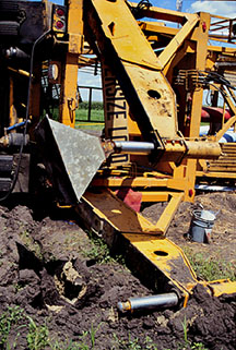
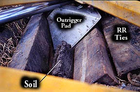
The investigation concluded that the tower crane fell directly in line with, and on top of, the right rear outrigger, complete failure of the ground under the right rear outrigger occurring soon after the full load was upon it. Although the top of the ground in the area was dry, deeper soil under the three timbers was wet and soft. The weight of the load squeezed this soil upward between the timbers (See Photo 6). There was a depression approximately 18 inches deep in the ground made from the right rear dual tires of the trailer (See Photo 7). This depression was evidently made when the outrigger failed and the complete weight of the hoisted load and the crane was momentarily transferred to the trailer before the tower fell flat to the ground.
CAUSE OF DEATH
The official cause of death from the Medical Examiner's report was, "massive head, chest, and abdominal trauma."
RECOMMENDATIONS / DISCUSSION
Recommendation #1: Crane owners and operators should ensure that cranes are properly set up with the outrigger pads supported by firm stable footing.
 Discussion: Construction projects frequently require the use of a mobile
crane which must be set up on soil that has recently been worked
or backfilled for foundations, grading, etc. In addition, it is
not unusual for crane operators to encounter frozen / partially
frozen soil, wet soil, layered soil, changing weather conditions,
etc. Because a crane’s lifting capacity increases as the
swing radius (distance from center of crane to lifted load) decreases,
crane operators desire to set up as close to the worksite as possible.
However, soil is frequently unstable in these locations and extra
precautions are necessary to provide firm stable footing.
Discussion: Construction projects frequently require the use of a mobile
crane which must be set up on soil that has recently been worked
or backfilled for foundations, grading, etc. In addition, it is
not unusual for crane operators to encounter frozen / partially
frozen soil, wet soil, layered soil, changing weather conditions,
etc. Because a crane’s lifting capacity increases as the
swing radius (distance from center of crane to lifted load) decreases,
crane operators desire to set up as close to the worksite as possible.
However, soil is frequently unstable in these locations and extra
precautions are necessary to provide firm stable footing.
An evaluation of the outrigger loading based on information obtained from the crane manufacturer’s operating manual indicated that the ground under the rear outriggers was subjected to a pressure of about 3600 psf.., which is 1600 psf.. greater than the soil's certified 2000 psf.. capacity. See appendix for a more detailed description of the evaluation. Evidence at the incident site noted in Photos 4, 5, and 6, confirms that the ground was failing under the outriggers just prior to the incident. When the crane had been set up adjacent to the water tower, the rear outriggers had been set on three; 12-inch by 7-inch by 85-inch cribbing timbers, providing a bearing area of just over 21 square feet. To reduce the loading to a level of 2000 psf.., it would have been necessary to increase the bearing area to about 39 square feet. This could have been accomplished by using appropriately sized steel or timber mats under the outrigger pads. In either case, the services of a certified professional engineer should be consulted to assure that the mats are of sufficient size and strength to support the crane and its load.
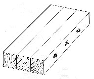 Contributing
to the occurrence of the incident was the manner in which the
timbers were placed under the outriggers. As can be seen in Photos
4, 5, and 6, just prior to the incident, the cribbing timbers
were rolling out from under the outrigger pads and spreading away
from each other. Some crane companies we consulted always use
plywood or steel plates under outrigger timbers to minimize shifting
of the soil and/or cribbing rollout, even if they are setting
up on highway concrete. In addition, some operators use long bolts
through timbers to create a solid base, to prevent cribbing rollout
(See Figure)
Contributing
to the occurrence of the incident was the manner in which the
timbers were placed under the outriggers. As can be seen in Photos
4, 5, and 6, just prior to the incident, the cribbing timbers
were rolling out from under the outrigger pads and spreading away
from each other. Some crane companies we consulted always use
plywood or steel plates under outrigger timbers to minimize shifting
of the soil and/or cribbing rollout, even if they are setting
up on highway concrete. In addition, some operators use long bolts
through timbers to create a solid base, to prevent cribbing rollout
(See Figure)
In this case, it is apparent that the rear outriggers were setup improperly. The ground was not leveled under the outrigger, and cribbing timbers were not placed close together, nor were other means taken to prevent cribbing rollout. It appears that much of the hoisted load was transferred to the middle timber, which was certainly not adequate to support the load. More significantly, adequate bearing area to reduce the outrigger loading below 2000 psf.. may have prevented this incident.
Recommendation # 2: Crane set-ups should be closely observed during lifting operations to detect instability caused by changing load and ground conditions.
Discussion: Evaluation of the incident circumstances indicates that the ground under the right rear outrigger had begun to fail early in the lift. As evidenced by Photo 4, the ground under the outrigger was already failing, yet the hoisted load was less than waist high above the ground. Had the ground condition under the outrigger been detected and correctly assessed at this point, there would have been time to lower the load and change the outrigger set up to one that was more stable. During the lift there were several workers on the ground, including the owner of the tank company and the foreman of the crane crew. Once the lift was begun, it lasted about 11 minutes, during which the ground under the outrigger continued to fail to the point that the lean of the crane caused it to become unstable and it fell over. It seems likely that the attention of ground observers would be focused on the lifted load and the workers on the water tower. However, as a crane lifts and then swings its load into position, the outrigger loading changes, increasing as the load is swung over them. To detect potentially unstable conditions, the entire crane setup should be observed during a lift.
Recommendation # 3: Prior to crane operations, construction companies utilizing crane services as well as the crane owners and operators should evaluate the soil bearing capacity at the lift site to ensure that crane equipment and procedures are compatible with site conditions.
Discussion: Prior to the incident, there was information available that if it had been evaluated could have indicated the need for additional measures or the use of alternate lifting methods. The sub-soil characteristics, including a 2000 psf.. bearing capacity, had been identified two months prior to the lift. The crane operating manual contained information from which outrigger loading could be estimated. The crane company had experienced a similar incident in 1997, in which the soil bearing capacity had not been properly considered when establishing the practical working load of the crane. In both instances the failing outrigger was setup on backfilled topsoil, which has no approved load-bearing rating. Evaluation of this information may have indicated that the crane and/or the lift procedures were incompatible with the site conditions. It is not known if each of the companies involved in this incident were aware of all the information available. However, if the information had been shared and correctly evaluated, the need for additional measures to ensure crane stability or the use of an alternative type of crane may have been recognized.
Additional Sources of Information
Much can be learned from the experience of other crane operators around the country. WWW.craneaccidents.com was created for this purpose, and is a lively forum to keep abreast of developments, stories, accidents, opinions, etc. The tower crane involved in this fatality was over 20 years old, and identical units are successfully being used by other crane operators in the USA. As more and more dialog takes place, operators will become aware of crane hazards and adopt better habits of safety.
| ___________________________________ | __________________________________ |
| Wayne Johnson, M.D. | Risto Rautiainen, M.Sc.Agr. |
| Trauma Investigator (FACE) | Coordinator |
| Institute for Rural & Environmental Health | Great Plains Center for Agricultural Health |
| University of Iowa -- Iowa City, Iowa | Institute for Rural & Environmental Health |
| University of Iowa -- Iowa City, Iowa |
Evaluation of Rear Outrigger Loads
The outrigger loading, or the pressure exerted by the outrigger against the supporting ground, depends on the load imposed on the outrigger by the weight of the crane and the lifted load and the bearing area, the surface area between the outrigger set up and the ground. The resulting pressure can be calculated using the formula:
P = F/A
Where: P is the pressure in pounds per square foot (psf.), F is the load on the outrigger in pounds (lbs), and A is the bearing area in square feet (sq.ft.).
The manufacturer's operating manual for the crane in this incident includes charts that contain values of outrigger loads for various weights of lifted loads. These tables list total load on each rear outrigger according to the load being lifted.
The tables do not list values for loads generated by a lifted load of 28,000 lbs, the empty weight of the tank. However, the table lists a total load of 74,000 lbs for a 20,000 lbs lifted load and a total outrigger load of 78,000 lbs for a 30,000 lb lifted load. By interpolating between these two values, the total load on each rear outrigger resulting from a 28,000 lb lifted load can be estimated to be about 77,200 pounds.
The rear outriggers of the crane in the incident had been set up on 3; 12-inch wide by 7-inch high by 85-inch long timbers providing a bearing area of 21.25 sq. ft.
The resulting outrigger loading can be estimated using the previously mentioned formula:
P = 77,200 lbs/ 21.25 sq. ft.
P = 3632.9 psf. ~ 3600 psf.
The resulting outrigger loading of 3600 psf., is 1600 psf. above the certified 2000 psf. soil capacity at the indicent site.
By using the formula P=F/A, and solving for A, the increased bearing area necessary to reduce the outrigger loading to a level below 2000 psf. can be determined.
A = F/P
A= 77,200 lbs / 2000 psf.
A = 38.6 psf. ~39 sq. ft.
This should be considered the minimum bearing area needed.